
LOW COST MOBILE SOLUTIONS FOR VAPOR RECOVERY AND DEGASSING
PORTABLE, CUSTOM FLARES AND COMBUSTERS

SHORT NOTICE MOBILIZATIONS TO ANYWHERE IN THE US

CUSTOM DOCK SAFETY SKIDS, USCG COMPLIANT

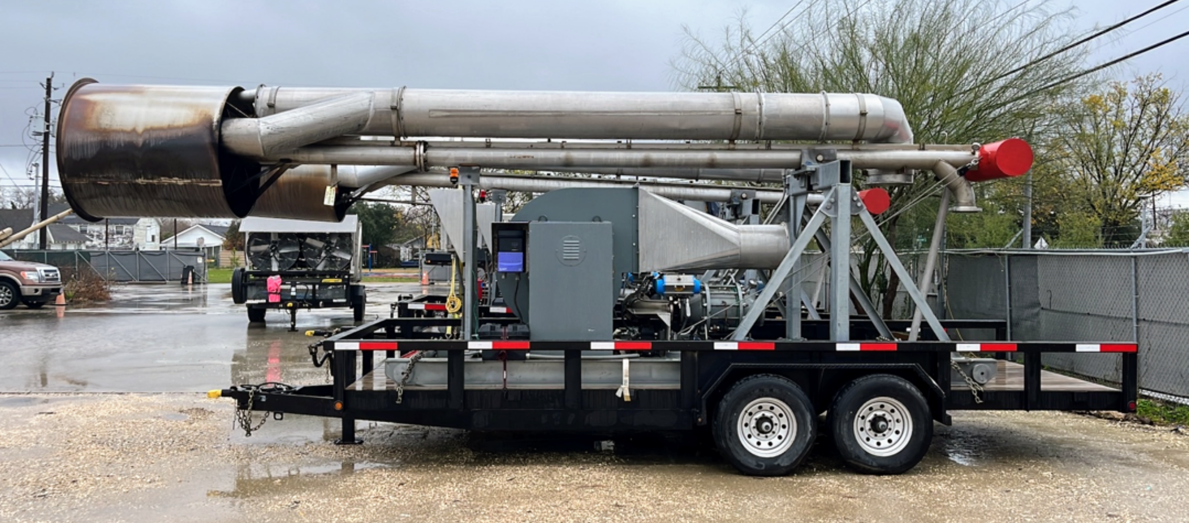
MOBILE CRYROGENIC VAPOR RECOVERY SYSTEM

FLEET OF VAPORIZERS OF ALL SIZES: NH3, LIN, CO2, LPG & MORE
Cryogenic Vapor Recovery Sytem
PATENTED, UNIQUE, LIQUID NITROGEN COOLED MOBILE CONDENSING SYSTEM
USCG approved vapor control system
ZERO emissions, save your air permit!
Ideal for chlorinated solvents and VOC cargoes like gasoline.
No Flame significantly reduces fire & explosion risk. Class 1 DIV 2
Eliminate recordable VOC and CO2 emissions from degassing events.
Eliminate risk of unintentional release to atmosphere and risk of sending liquid to flare
Condense, collect, recycle. PURGIT recovered 1.75 million pounds of VOC that otherwise would have been burned. Carbon emission credits may be available.
Learn more about PURGIT’s refrigerated vapor recovery system
Comprehensive Turn-Key Solutions
Tailored services: Custom made vapor control solutions to meet all customer needs
Specialty equipment:
Custom made flares, designed in-house, currently on 5th design revision building on previous lessons learned
Custom dock safety skid for unloading operations at ports
Custom fleet of vaporizers of all sizes for liquid propane, ammonia, nitrogen, CO2, and others
Unmatched Mobility: Highly mobile fleet ready to deploy anywhere in the US and Canada on short notice, including emergency mobilizations for customer incidents
FIND OUT MORE
Call us to discuss our services